Residential design study

The whole
set is open.

130 original sheets from the current drawing framework. Explore each discipline and inspect the source model beside the output.

Explore the Building
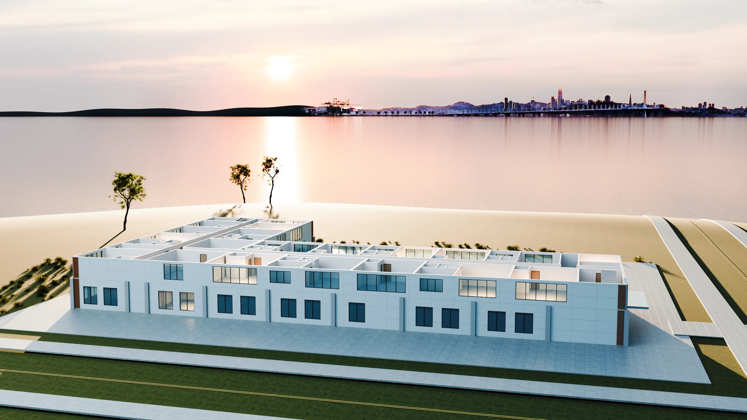
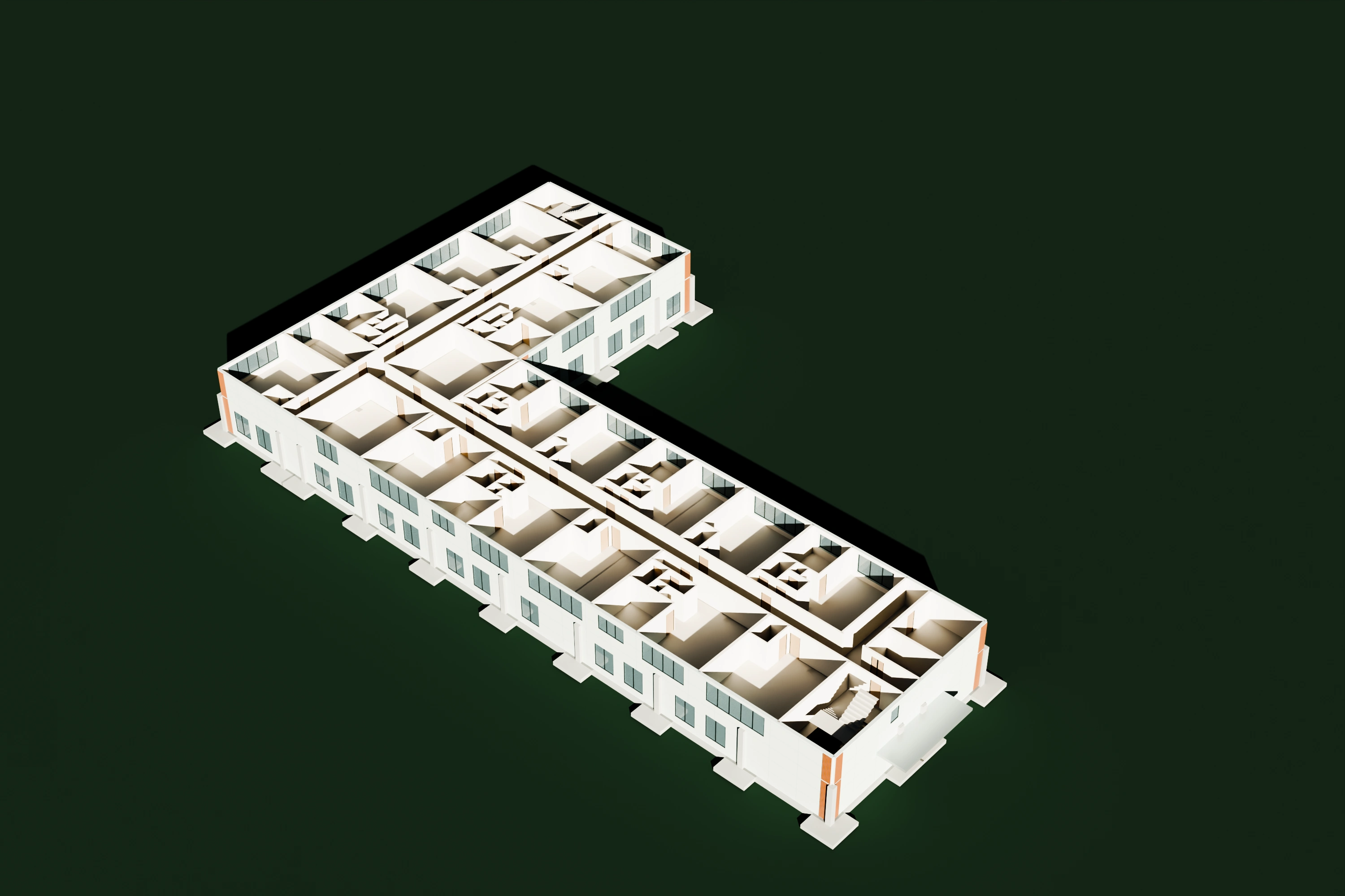
The source building with upper levels removed to expose its occupied rooms and common corridor
Open building · Source rooms and circulationView Rendering Record ↗
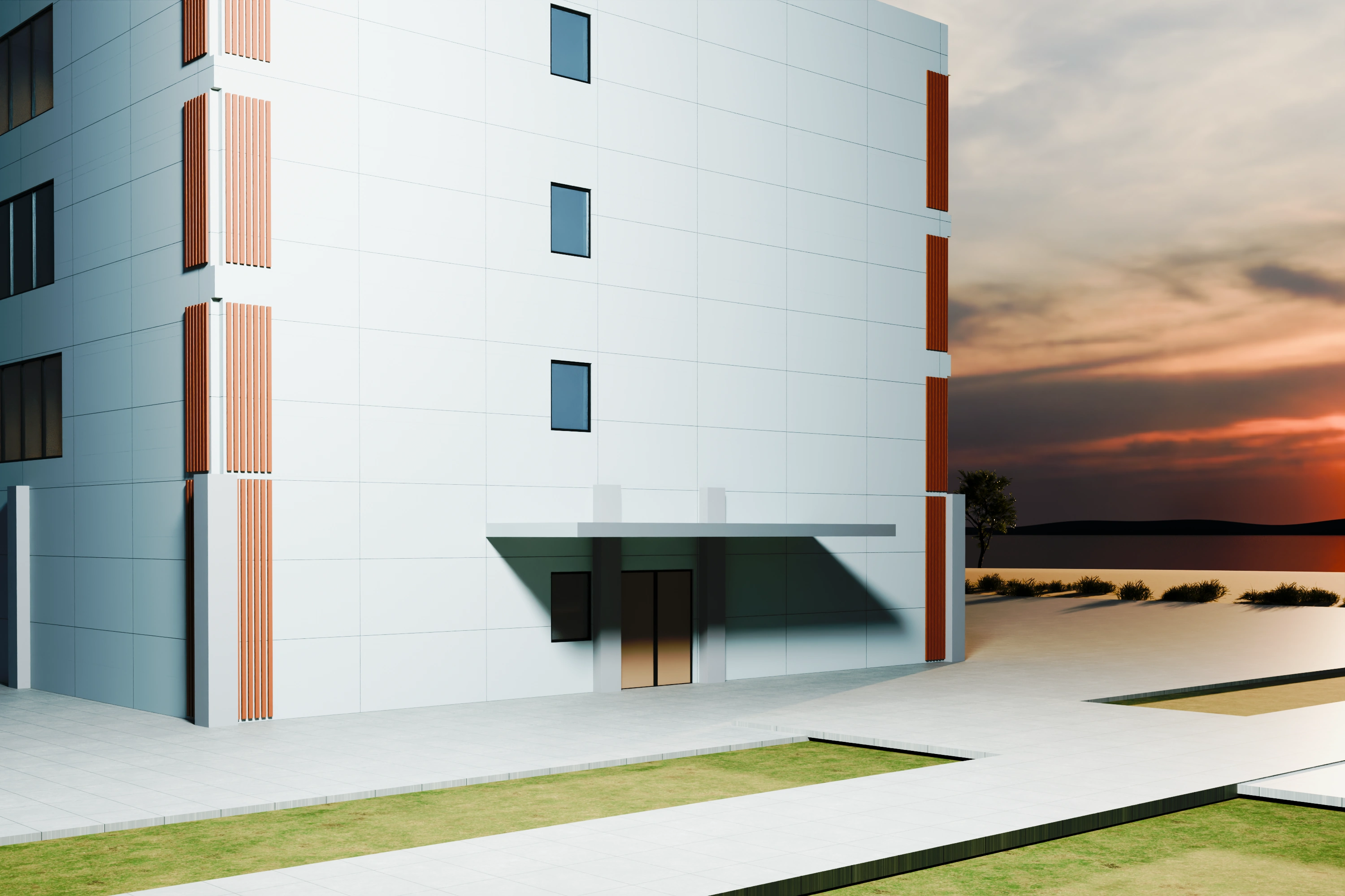
East entrance canopy and paired doors rendered from the source building model
East entrance · Source canopy and paired doors
The lower two source levels opened to show rooms, doors and the common corridor
Lower two levels · Source rooms and circulation
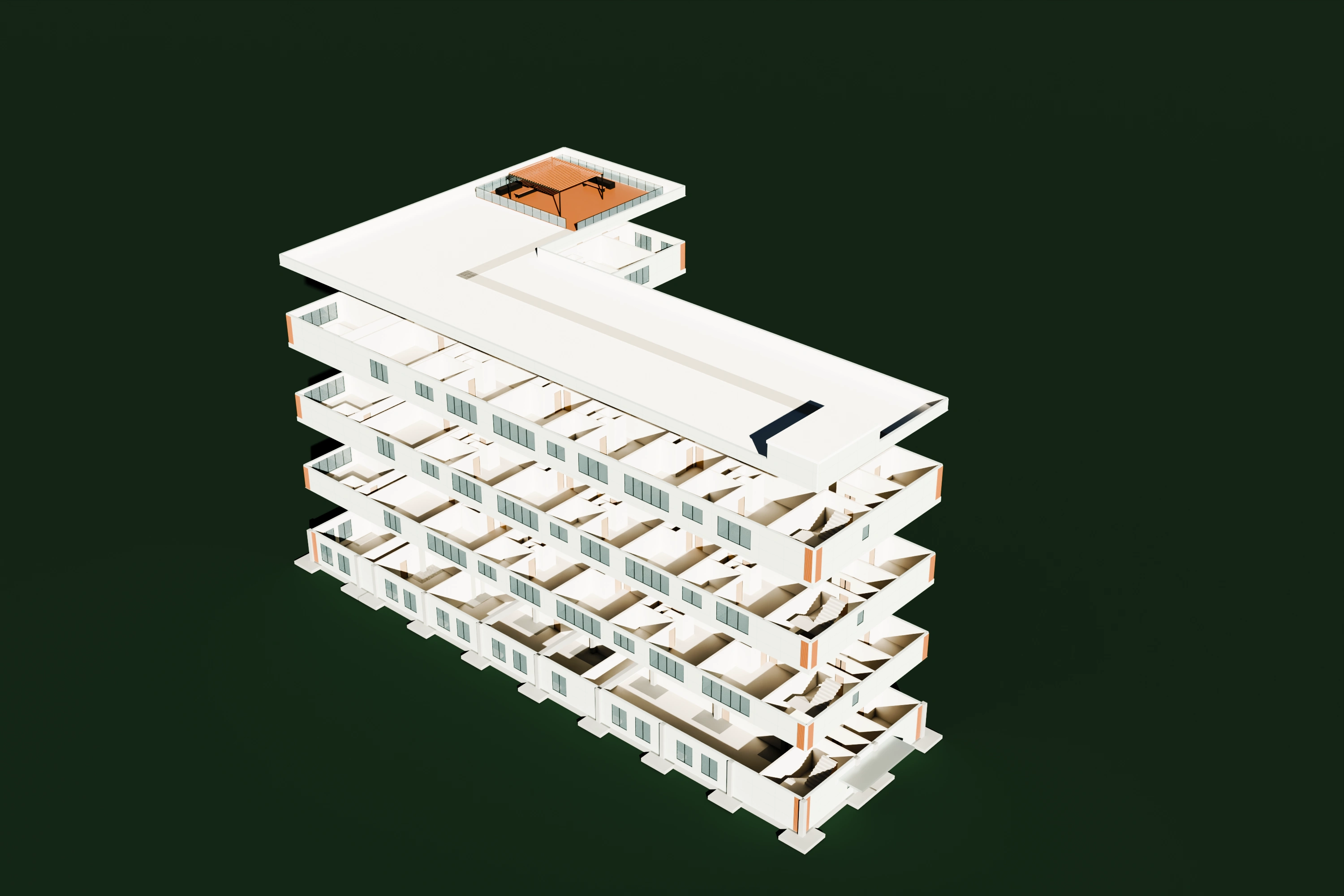
Source building levels separated vertically to show their relationship
Separated levels · Display offsets onlyView Rendering Record ↗

130 original sheets · Current framework
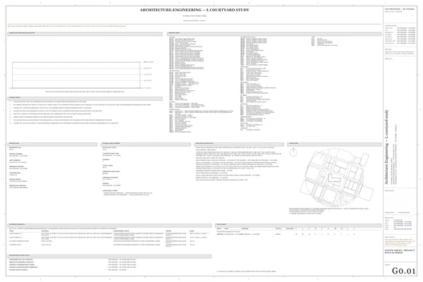
G0.01 Cover Sheet, Project Data & Index
G0.01Cover Sheet, Project Data & Index
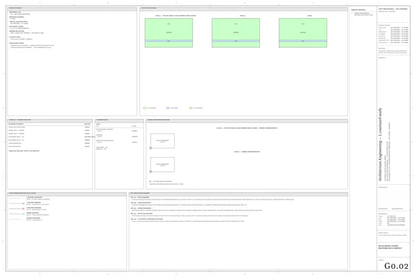
G0.02 Building Code Reference Sheet
G0.02Building Code Reference Sheet
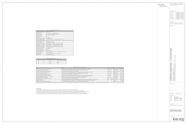
G0.03 Preliminary Code and Access Ledger
G0.03Preliminary Code and Access Ledger
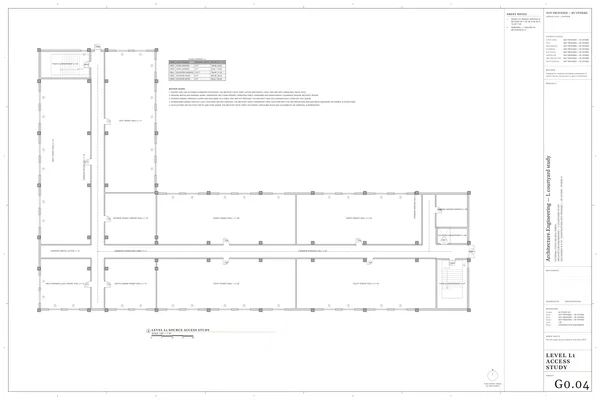
G0.04 Level L1 Access Study
G0.04Level L1 Access Study
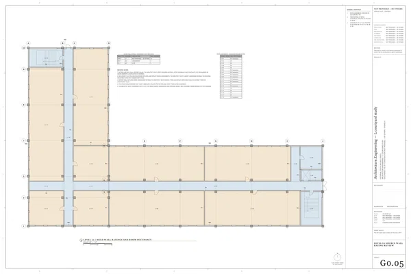
G0.05 Level L1 Source Wall Rating Review
G0.05Level L1 Source Wall Rating Review
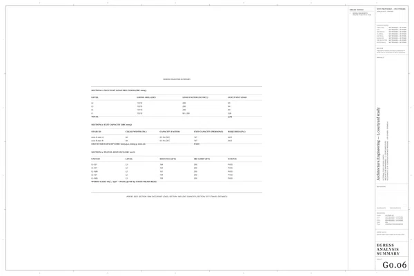
G0.06 Egress Analysis Summary
G0.06Egress Analysis Summary
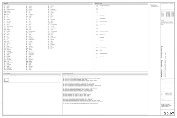
G0.07 Abbreviations, Symbols & General Information
G0.07Abbreviations, Symbols & General Information
G0.08 Energy Compliance
G0.08Energy Compliance
G0.09 General Construction Notes
G0.09General Construction Notes
G0.10 Material Specifications & Referenced Standards
G0.10Material Specifications & Referenced Standards
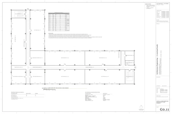
G0.11 Level L1 Preliminary Occupancy and Egress
G0.11Level L1 Preliminary Occupancy and Egress
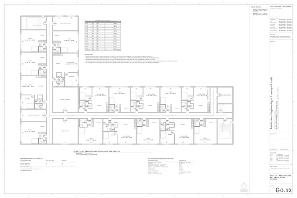
G0.12 Level L2 Preliminary Occupancy and Egress
G0.12Level L2 Preliminary Occupancy and Egress
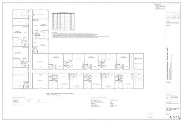
G0.13 Level L3 Preliminary Occupancy and Egress
G0.13Level L3 Preliminary Occupancy and Egress
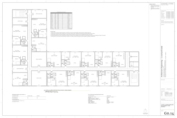
G0.14 Level L4 Preliminary Occupancy and Egress
G0.14Level L4 Preliminary Occupancy and Egress
G0.15 Level RF Preliminary Occupancy and Egress
G0.15Level RF Preliminary Occupancy and Egress
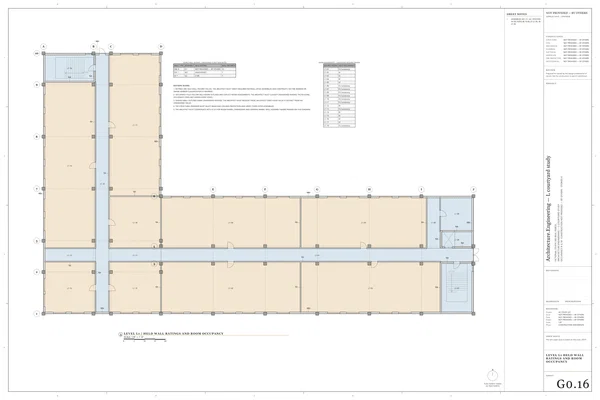
G0.16 Level L1 Held Wall Ratings and Room Occupancy
G0.16Level L1 Held Wall Ratings and Room Occupancy
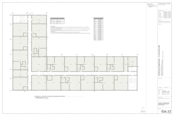
G0.17 Level L2 Held Wall Ratings and Room Occupancy
G0.17Level L2 Held Wall Ratings and Room Occupancy
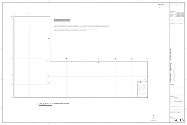
G0.18 Level RF Held Wall Ratings and Room Occupancy
G0.18Level RF Held Wall Ratings and Room Occupancy
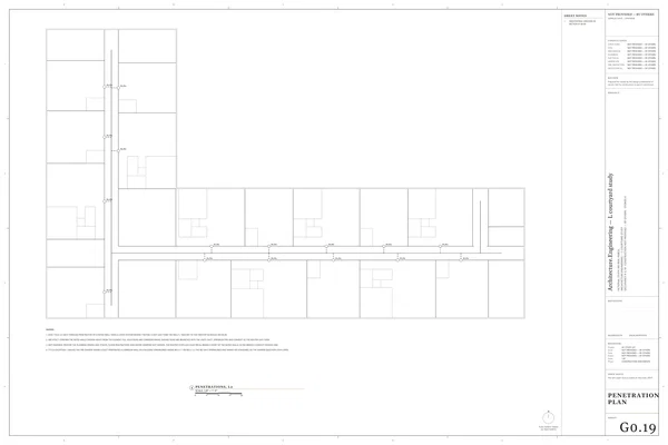
G0.19 Penetration Plan
G0.19Penetration Plan
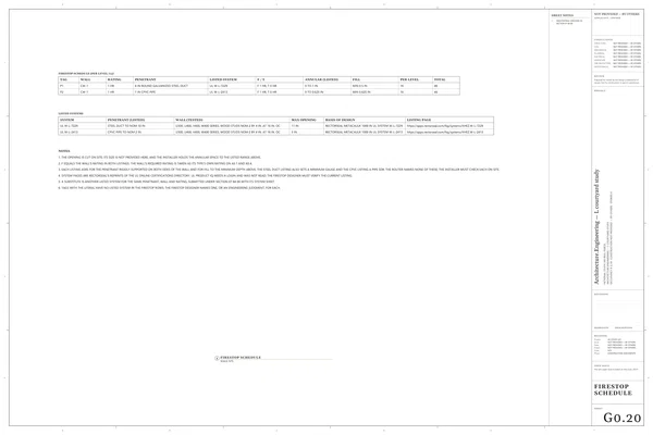
G0.20 Firestop Schedule
G0.20Firestop Schedule
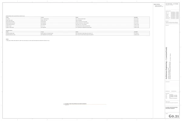
G0.21 Flood and Wildfire Hazard Screen
G0.21Flood and Wildfire Hazard Screen
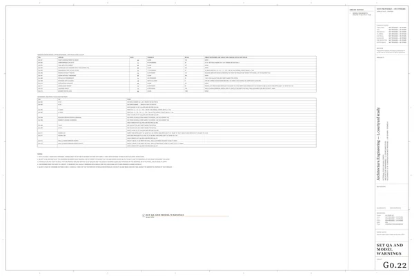
G0.22 Set QA and Model Warnings
G0.22Set QA and Model Warnings
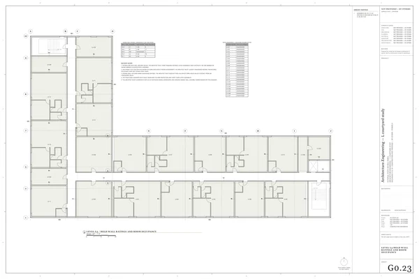
G0.23 Level L3 Held Wall Ratings and Room Occupancy
G0.23Level L3 Held Wall Ratings and Room Occupancy
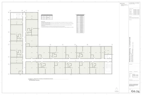
G0.24 Level L4 Held Wall Ratings and Room Occupancy
G0.24Level L4 Held Wall Ratings and Room Occupancy
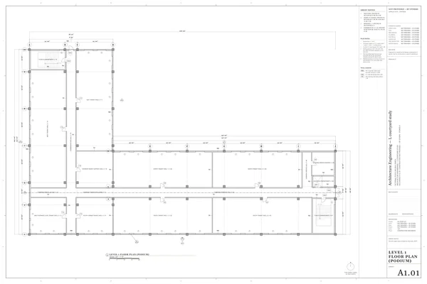
A1.01 Level 1 Floor Plan (Podium)
A1.01Level 1 Floor Plan (Podium)
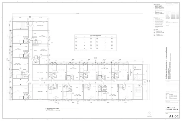
A1.02 Level L2 Floor Plan
A1.02Level L2 Floor Plan
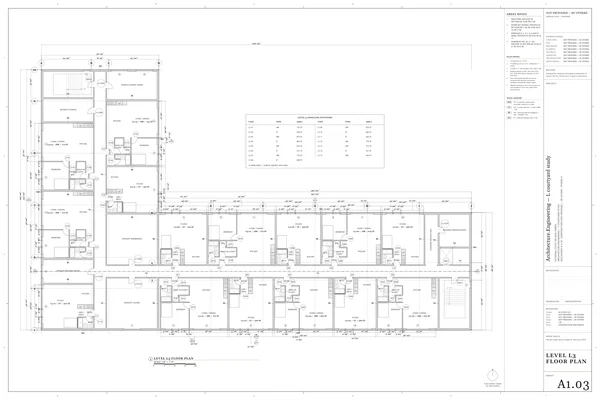
A1.03 Level L3 Floor Plan
A1.03Level L3 Floor Plan
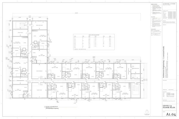
A1.04 Level L4 Floor Plan
A1.04Level L4 Floor Plan
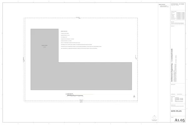
A1.05 Site Plan
A1.05Site Plan
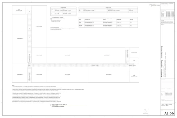
A1.06 Level L1 Reflected Ceiling Plan
A1.06Level L1 Reflected Ceiling Plan
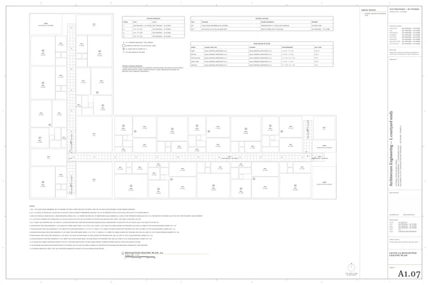
A1.07 Level L2 Reflected Ceiling Plan
A1.07Level L2 Reflected Ceiling Plan
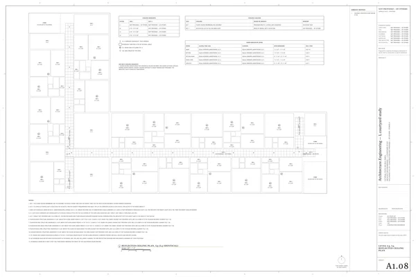
A1.08 Level L3, L4 Reflected Ceiling Plan
A1.08Level L3, L4 Reflected Ceiling Plan
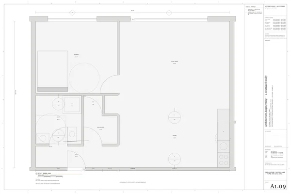
A1.09 Enlarged Unit Plans — Type 1BR (772 SF)
A1.09Enlarged Unit Plans — Type 1BR (772 SF)
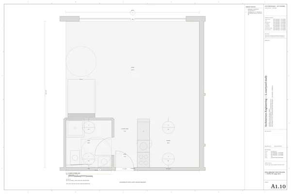
A1.10 Enlarged Unit Plans — Type ST (531 SF)
A1.10Enlarged Unit Plans — Type ST (531 SF)
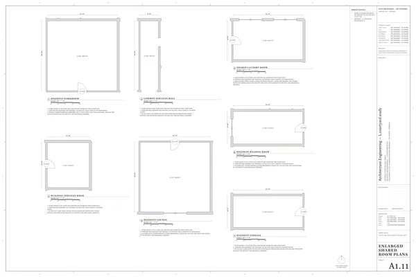
A1.11 Enlarged Shared Room Plans
A1.11Enlarged Shared Room Plans
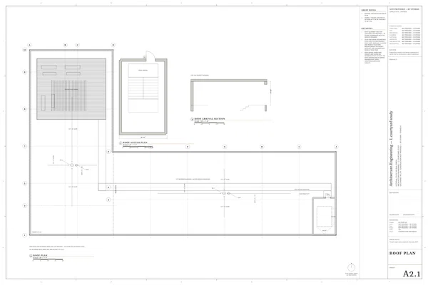
A2.1 Roof Plan
A2.1Roof Plan
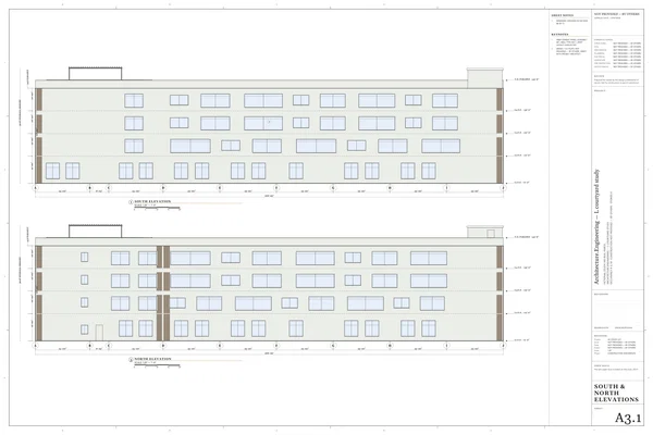
A3.1 South & North Elevations
A3.1South & North Elevations
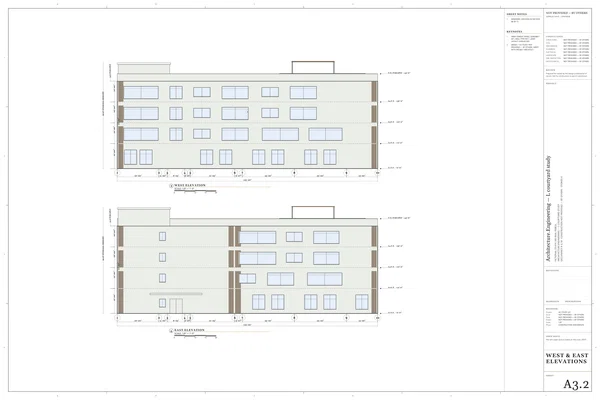
A3.2 West & East Elevations
A3.2West & East Elevations
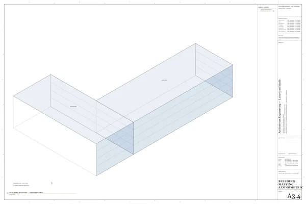
A3.4 Building Massing -- Axonometric
A3.4Building Massing -- Axonometric
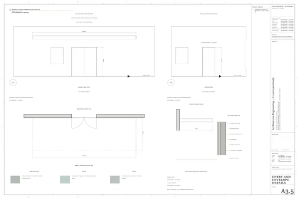
A3.5 Entry and Envelope Details
A3.5Entry and Envelope Details
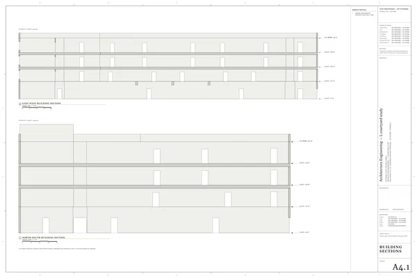
A4.1 Building Sections
A4.1Building Sections
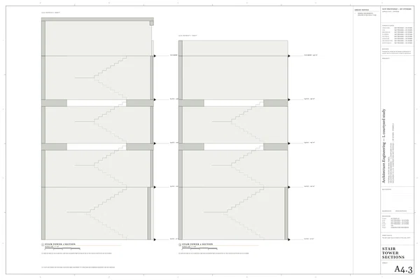
A4.3 Stair Tower Sections
A4.3Stair Tower Sections
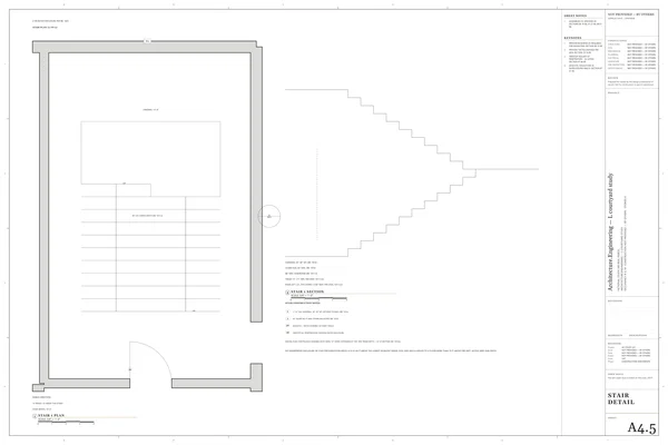
A4.5 Stair Detail
A4.5Stair Detail
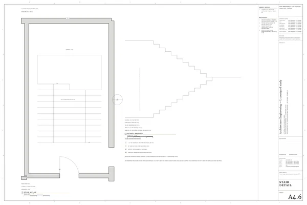
A4.6 Stair Detail
A4.6Stair Detail
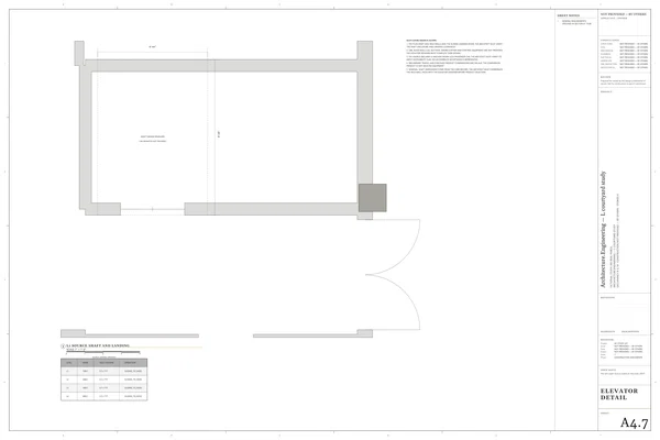
A4.7 Elevator Detail
A4.7Elevator Detail
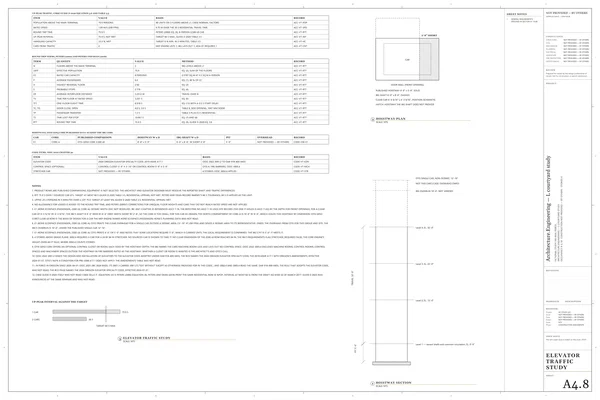
A4.8 Elevator Traffic Study
A4.8Elevator Traffic Study
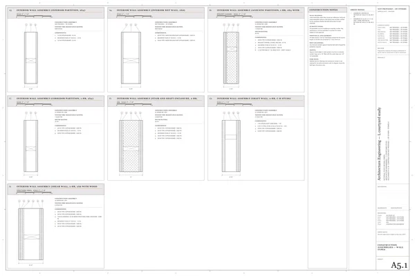
A5.1 Construction Assemblies — Wall Types
A5.1Construction Assemblies — Wall Types
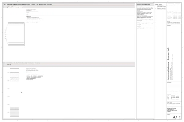
A5.2 Construction Assemblies — Floor/Ceiling & Shaft
A5.2Construction Assemblies — Floor/Ceiling & Shaft
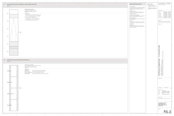
A5.3 Construction Assemblies — Roof/Ceiling & Column
A5.3Construction Assemblies — Roof/Ceiling & Column
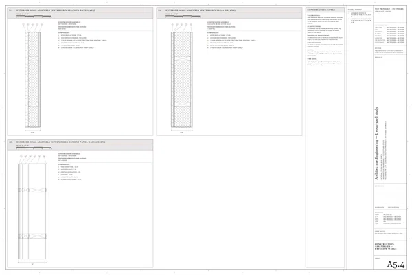
A5.4 Construction Assemblies — Exterior Walls
A5.4Construction Assemblies — Exterior Walls
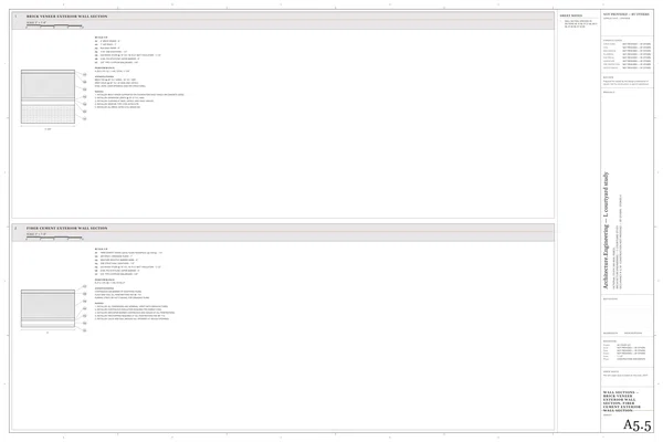
A5.5 Wall Sections — BRICK VENEER EXTERIOR WALL SECTION, FIBER CEMENT EXTERIOR WALL SECTION
A5.5Wall Sections — BRICK VENEER EXTERIOR WALL SECTION, FIBER CEMENT EXTERIOR WALL SECTION
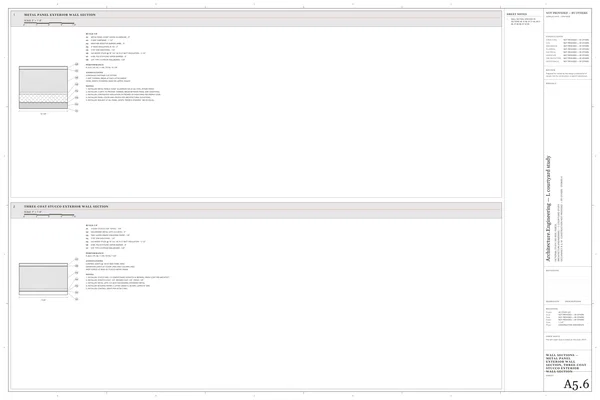
A5.6 Wall Sections — METAL PANEL EXTERIOR WALL SECTION, THREE-COAT STUCCO EXTERIOR WALL SECTION
A5.6Wall Sections — METAL PANEL EXTERIOR WALL SECTION, THREE-COAT STUCCO EXTERIOR WALL SECTION
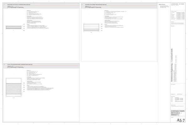
A5.7 Connection Details — Sheet 1
A5.7Connection Details — Sheet 1
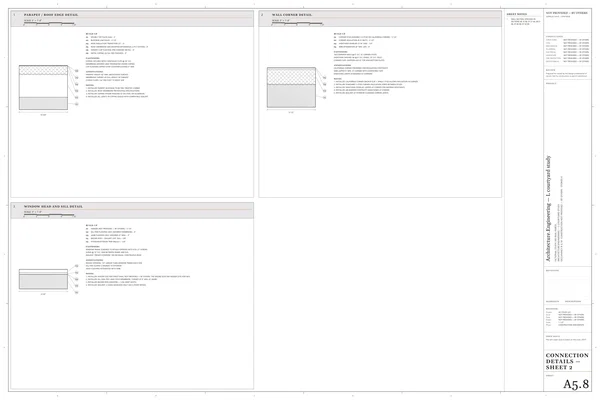
A5.8 Connection Details — Sheet 2
A5.8Connection Details — Sheet 2
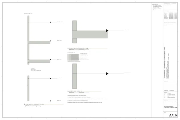
A5.9 Wall Section at Callout 1 and Details
A5.9Wall Section at Callout 1 and Details
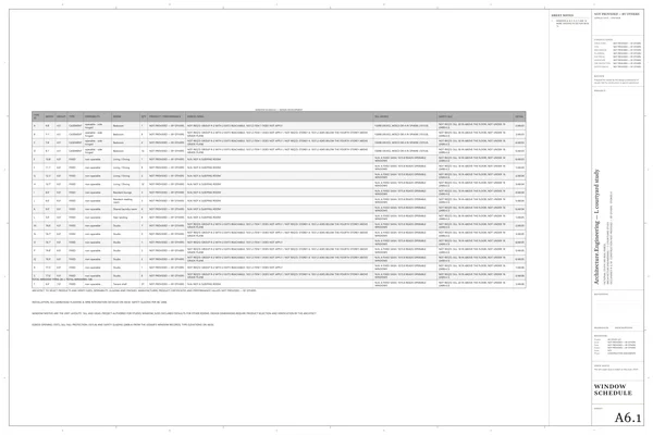
A6.1 Window Schedule
A6.1Window Schedule
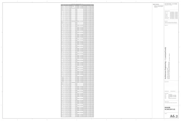
A6.2 Door Schedule
A6.2Door Schedule
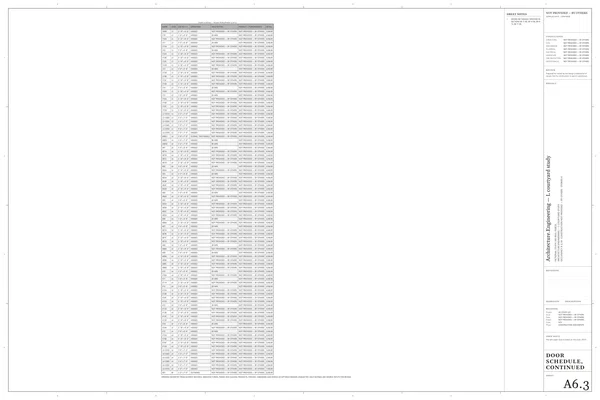
A6.3 Door Schedule, continued
A6.3Door Schedule, continued
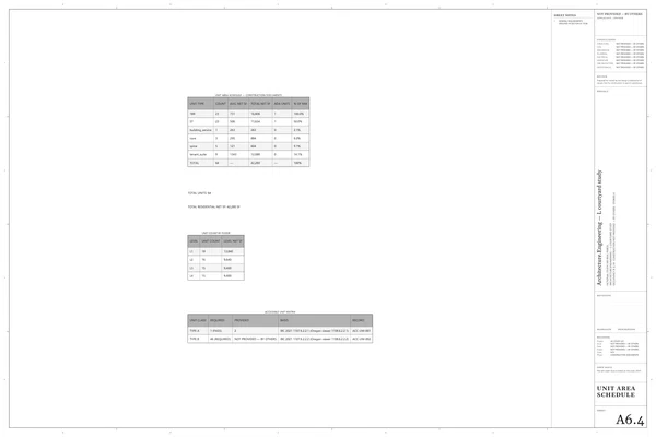
A6.4 Unit Area Schedule
A6.4Unit Area Schedule
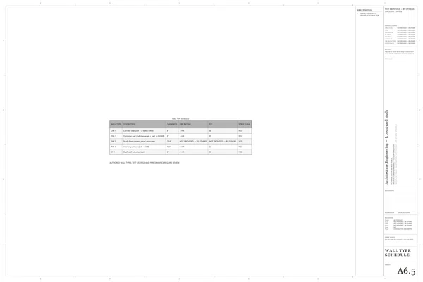
A6.5 Wall Type Schedule
A6.5Wall Type Schedule
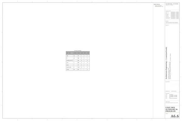
A6.6 Unit Mix Summary & Program
A6.6Unit Mix Summary & Program
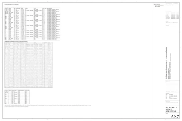
A6.7 Habitable Space Schedule
A6.7Habitable Space Schedule
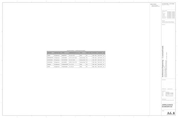
A6.8 Appliance Schedule
A6.8Appliance Schedule
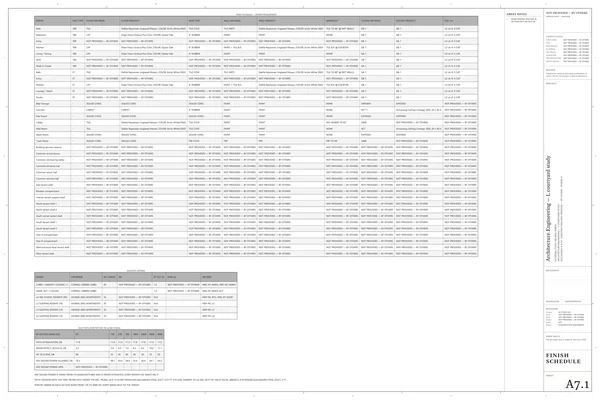
A7.1 Finish Schedule
A7.1Finish Schedule
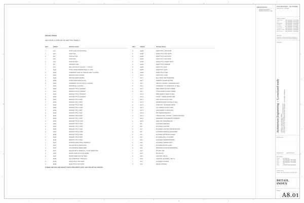
A8.01 Detail Index
A8.01Detail Index
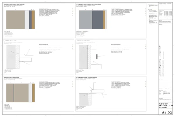
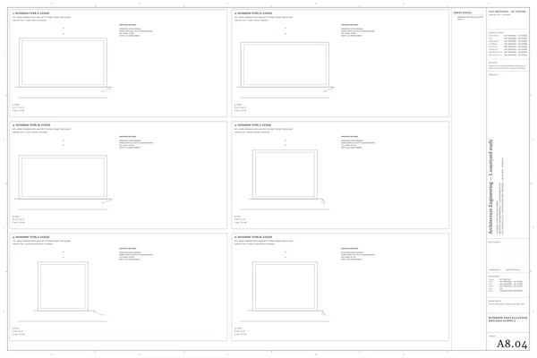
A8.02 Window Installation Details
A8.02Window Installation Details
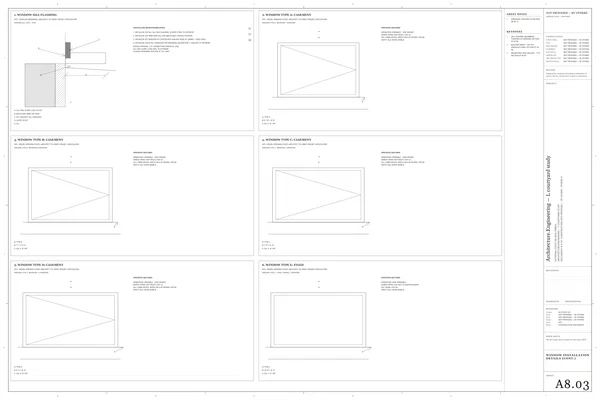
A8.03 Window Installation Details (CONT.)
A8.03Window Installation Details (CONT.)
A8.04 Window Installation Details (CONT.)
A8.04Window Installation Details (CONT.)
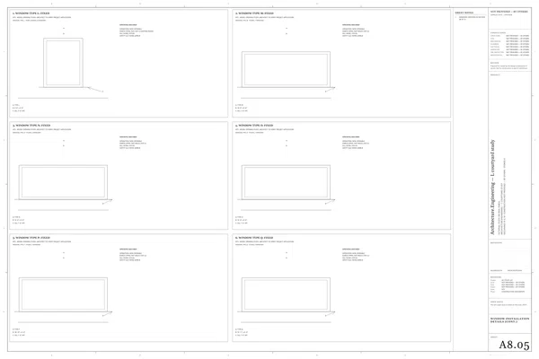
A8.05 Window Installation Details (CONT.)
A8.05Window Installation Details (CONT.)
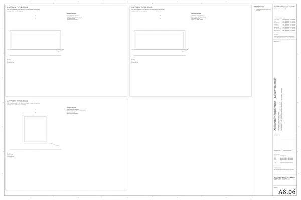
A8.06 Window Installation Details (CONT.)
A8.06Window Installation Details (CONT.)
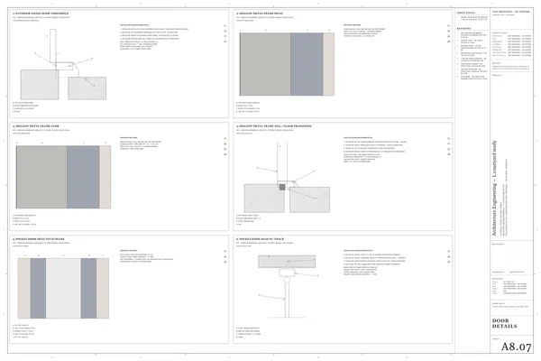
A8.07 Door Details
A8.07Door Details
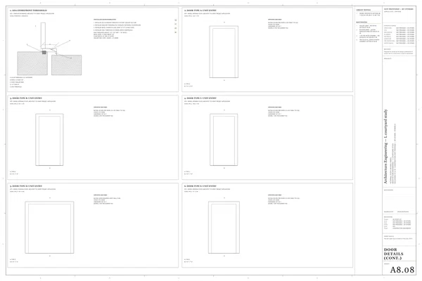
A8.08 Door Details (CONT.)
A8.08Door Details (CONT.)
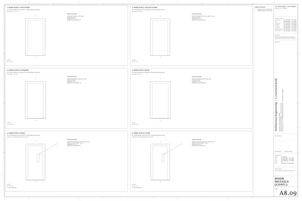
A8.09 Door Details (CONT.)
A8.09Door Details (CONT.)
A8.10 Door Details (CONT.)
A8.10Door Details (CONT.)
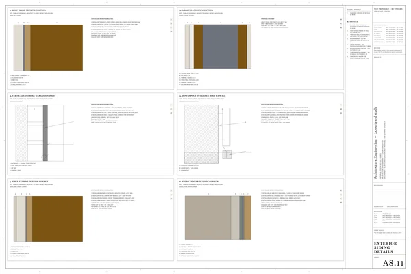
A8.11 Exterior Siding Details
A8.11Exterior Siding Details
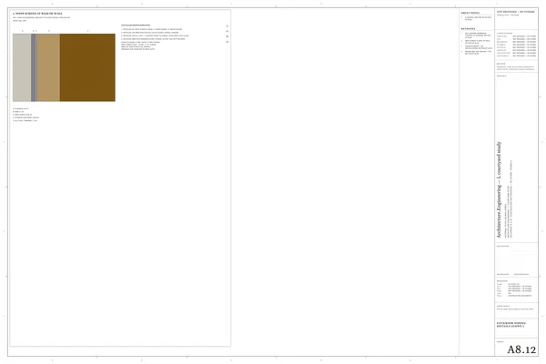
A8.12 Exterior Siding Details (CONT.)
A8.12Exterior Siding Details (CONT.)
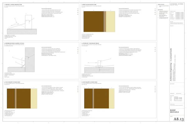
A8.13 Roof Details
A8.13Roof Details
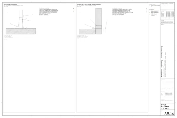
A8.14 Roof Details (CONT.)
A8.14Roof Details (CONT.)
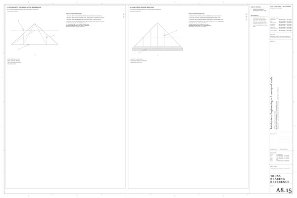
A8.15 Truss Bracing Reference
A8.15Truss Bracing Reference
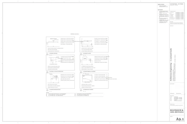
A9.1 Restroom & ADA Details
A9.1Restroom & ADA Details
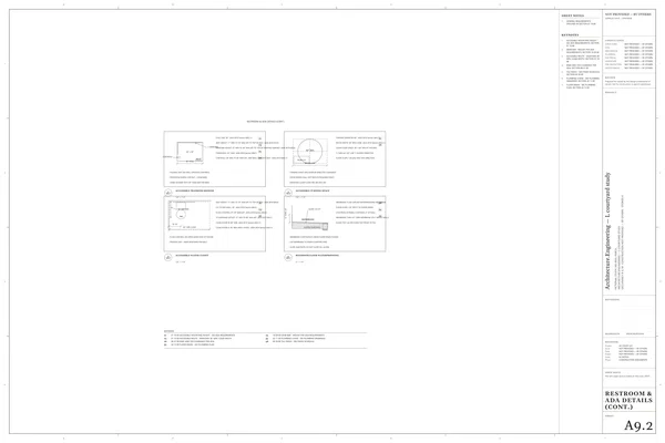
A9.2 Restroom & ADA Details (CONT.)
A9.2Restroom & ADA Details (CONT.)
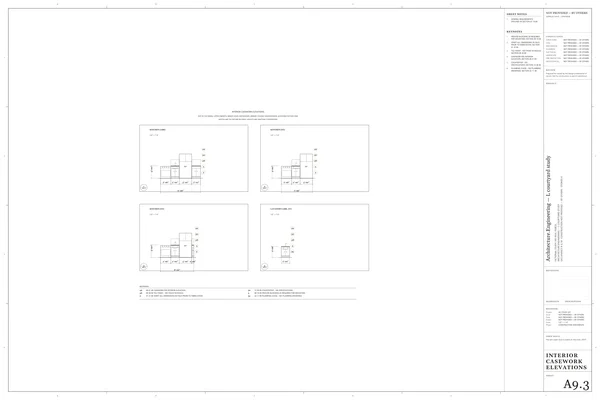
A9.3 Interior Casework Elevations
A9.3Interior Casework Elevations
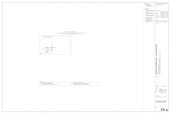
A9.4 Interior Casework Elevations (CONT.)
A9.4Interior Casework Elevations (CONT.)
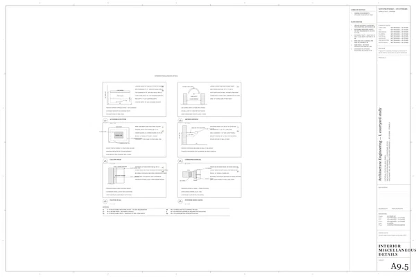
A9.5 Interior Miscellaneous Details
A9.5Interior Miscellaneous Details
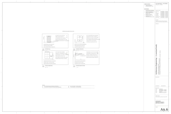
A9.6 Interior Miscellaneous Details (CONT.)
A9.6Interior Miscellaneous Details (CONT.)
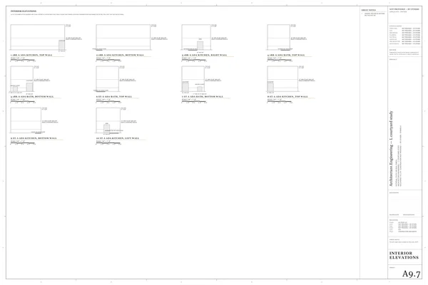
A9.7 Interior Elevations
A9.7Interior Elevations
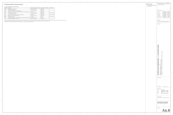
A9.8 Mounting Heights and Reach Ranges
A9.8Mounting Heights and Reach Ranges
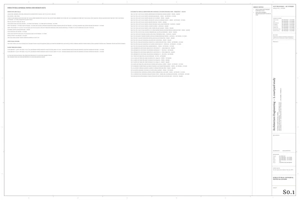
S0.1 Structural General Notes & Loads
S0.1Structural General Notes & Loads
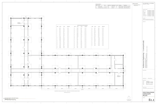
S1.1 Foundation Concept Plan
S1.1Foundation Concept Plan
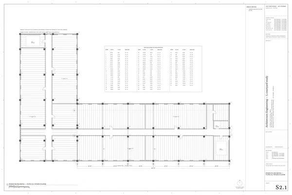
S2.1 Podium Framing + Typical Wood Floor
S2.1Podium Framing + Typical Wood Floor
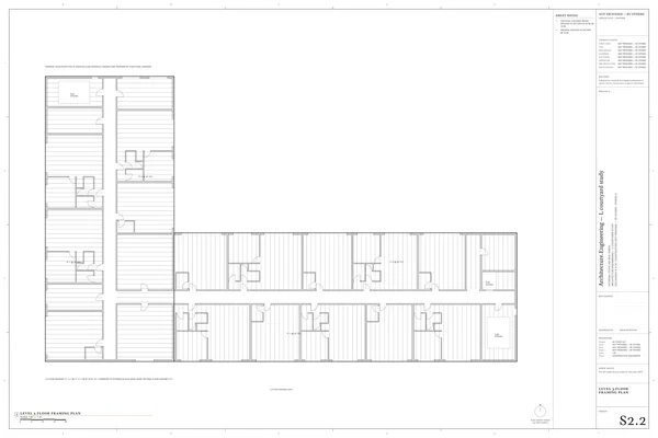
S2.2 Level 3 Floor Framing Plan
S2.2Level 3 Floor Framing Plan
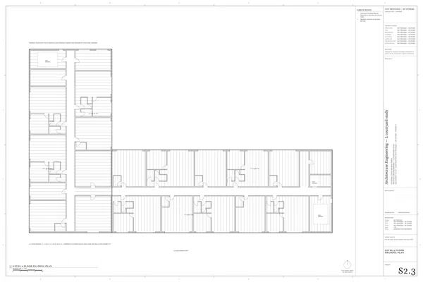
S2.3 Level 4 Floor Framing Plan
S2.3Level 4 Floor Framing Plan
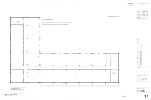
S3.1 Lateral System Concept
S3.1Lateral System Concept
S5.1 Seismic Forces and Bracing Schedule
S5.1Seismic Forces and Bracing Schedule
S5.2 MEP Bracing Plan
S5.2MEP Bracing Plan
S5.3 Seismic Bracing Details
S5.3Seismic Bracing Details
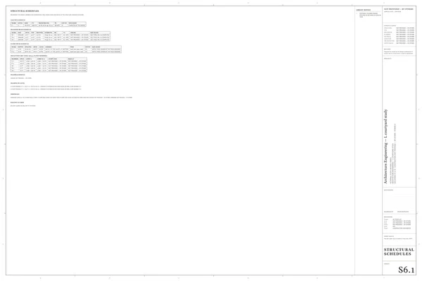
S6.1 Structural Schedules
S6.1Structural Schedules
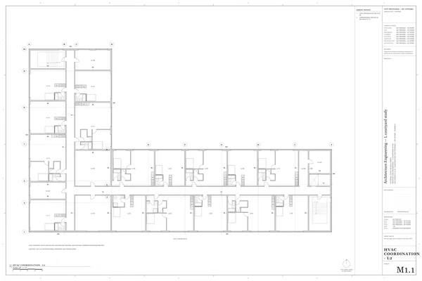
M1.1 Hvac Coordination - L2
M1.1Hvac Coordination - L2
M2.1 HVAC Load Calculations
M2.1HVAC Load Calculations
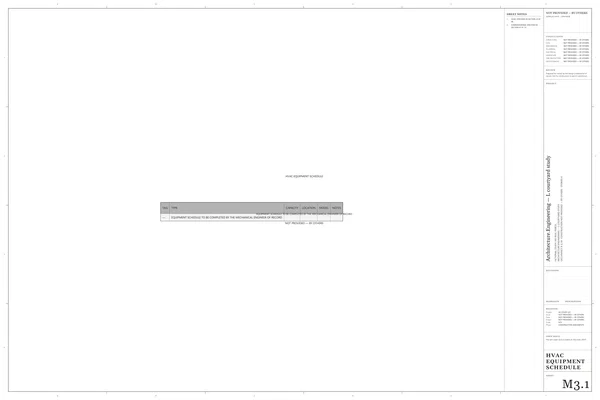
M3.1 HVAC Equipment Schedule
M3.1HVAC Equipment Schedule
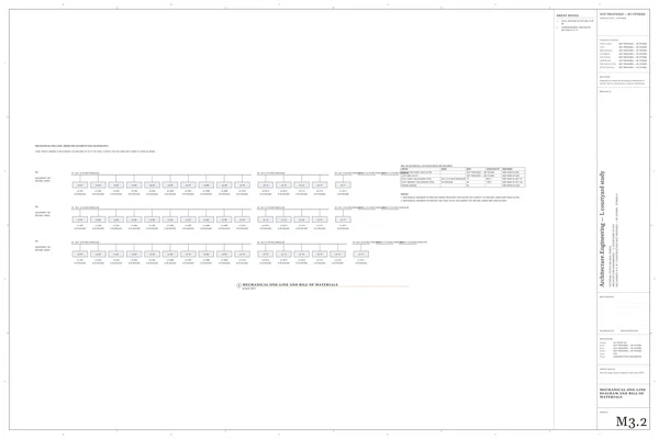
M3.2 Mechanical One-Line Diagram and Bill of Materials
M3.2Mechanical One-Line Diagram and Bill of Materials
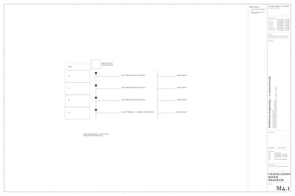
M4.1 Ventilation Riser Diagram
M4.1Ventilation Riser Diagram
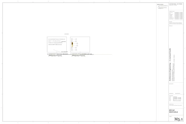
M5.1 HVAC Details
M5.1HVAC Details
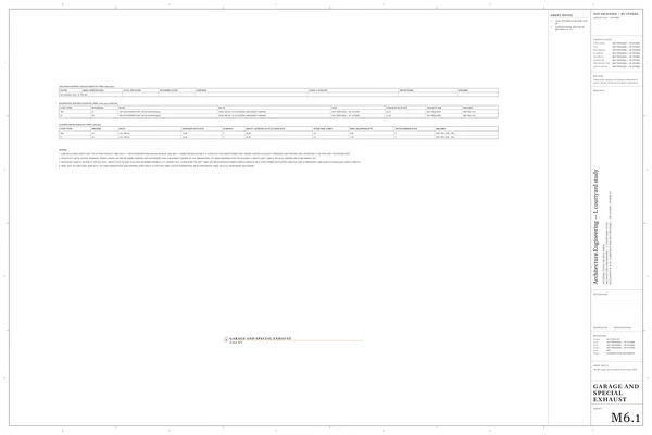
M6.1 Garage and Special Exhaust
M6.1Garage and Special Exhaust
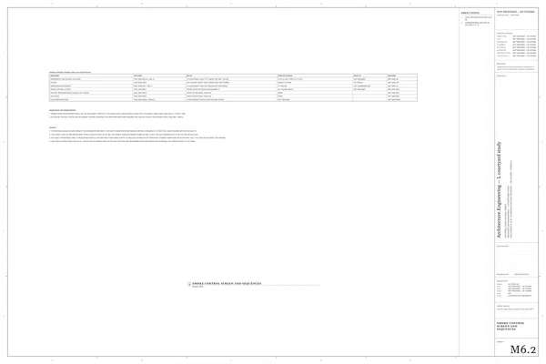
M6.2 Smoke Control Screen and Sequences
M6.2Smoke Control Screen and Sequences
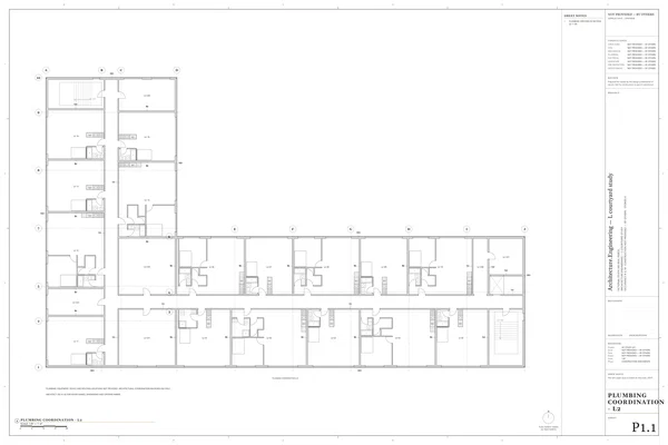
P1.1 Plumbing Coordination - L2
P1.1Plumbing Coordination - L2
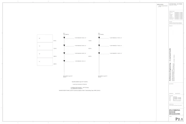
P2.1 Plumbing Riser Diagrams
P2.1Plumbing Riser Diagrams
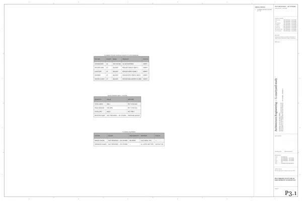
P3.1 Plumbing Fixture & Equipment Schedule
P3.1Plumbing Fixture & Equipment Schedule
P4.1 Plumbing Details
P4.1Plumbing Details
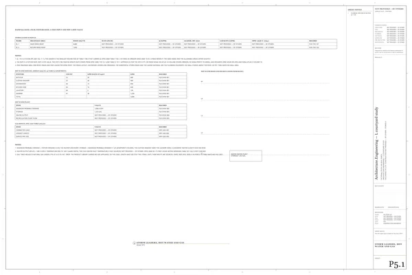
P5.1 Storm Leaders, Hot Water and Gas
P5.1Storm Leaders, Hot Water and Gas
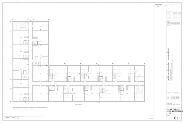
E1.1 Electrical Coordination - L2
E1.1Electrical Coordination - L2
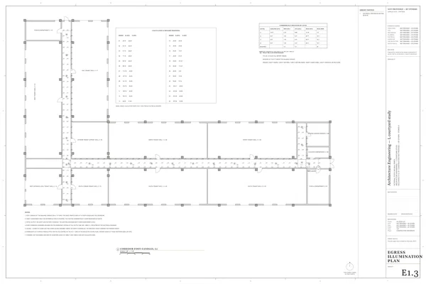
E1.3 Egress Illumination Plan
E1.3Egress Illumination Plan
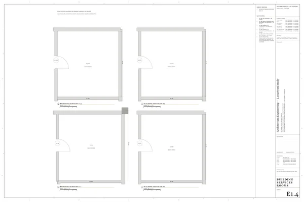
E1.4 Building Services Rooms
E1.4Building Services Rooms
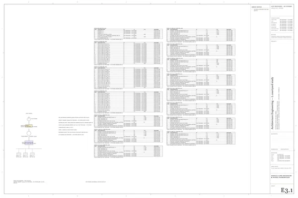
E3.1 Single-Line Diagram & Panel Schedules
E3.1Single-Line Diagram & Panel Schedules
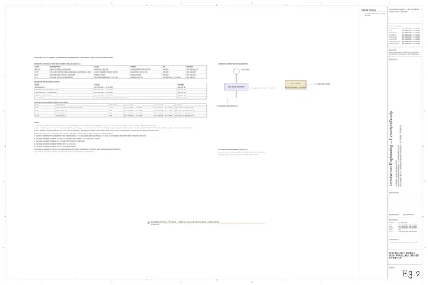
E3.2 Emergency Power and Available Fault Current
E3.2Emergency Power and Available Fault Current
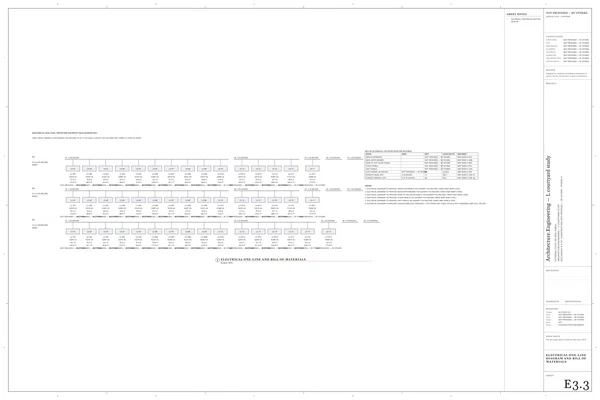
E3.3 Electrical One-Line Diagram and Bill of Materials
E3.3Electrical One-Line Diagram and Bill of Materials
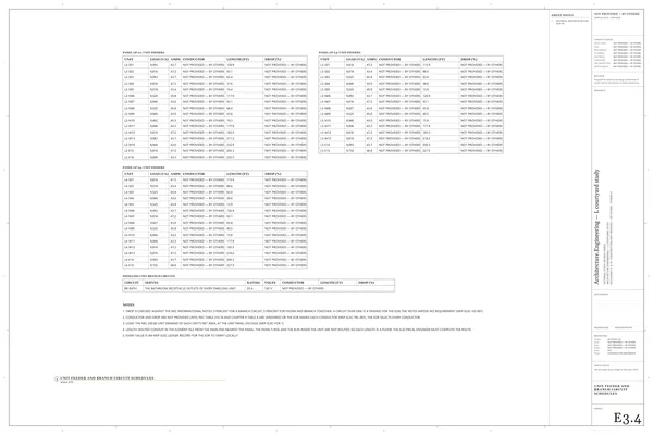
E3.4 Unit Feeder and Branch Circuit Schedules
E3.4Unit Feeder and Branch Circuit Schedules
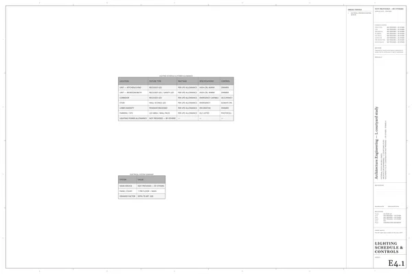
E4.1 Lighting Schedule & Controls
E4.1Lighting Schedule & Controls
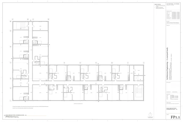
FP1.1 Fire Protection Coordination - L2
FP1.1Fire Protection Coordination - L2
FP2.1 Fire Sprinkler Riser Diagram
FP2.1Fire Sprinkler Riser Diagram
FP3.1 Fire Protection Design Basis
FP3.1Fire Protection Design Basis
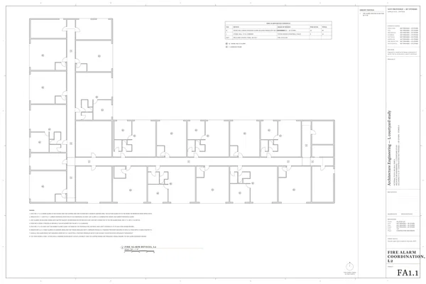
FA1.1 Fire Alarm Coordination, L2
FA1.1Fire Alarm Coordination, L2
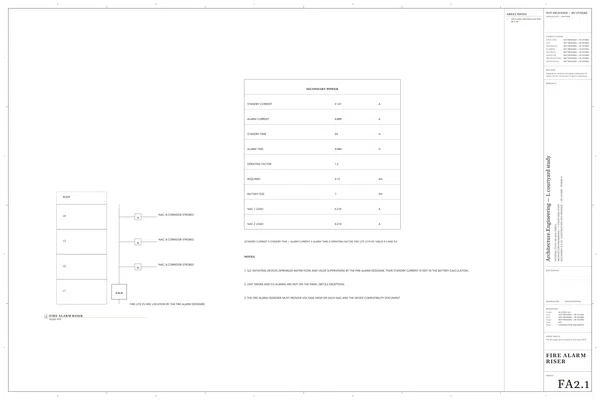
FA2.1 Fire Alarm Riser
FA2.1Fire Alarm Riser
L1.1 Landscape Coordination
L1.1Landscape Coordination
C1.1 Site Plan
C1.1Site Plan
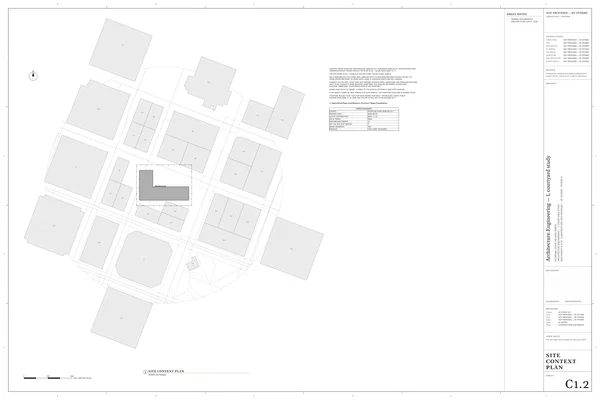
C1.2 Site Context Plan
C1.2Site Context Plan
C1.3 Fire Flow and Fire Access
C1.3Fire Flow and Fire Access
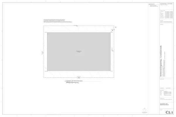
C2.1 Grading and Drainage Plan
C2.1Grading and Drainage Plan
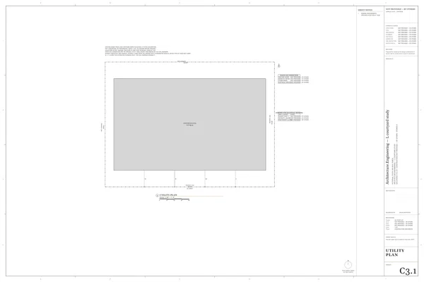
C3.1 Utility Plan
C3.1Utility Plan
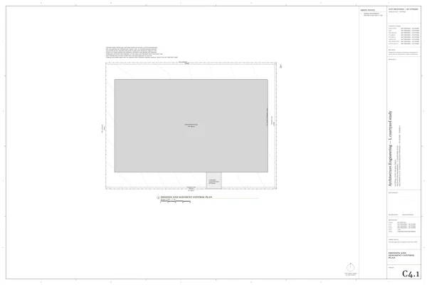
C4.1 Erosion and Sediment Control Plan
C4.1Erosion and Sediment Control Plan

Drawing

100%Original PDF ↗
Selected drawing

05 / Carry it forward

A set you
can question.

Open the source. Follow the changes.
Bring your own professional judgment.

Start a Project

This residential design study links the building you see to its source model and original drawings. It is a fictional project, with no surveyed parcel or permit approval.

Read the review findings
  • Fictional architectural study with an illustrative San Francisco setting; no surveyed parcel or permit approval.
  • San Francisco is the visual setting. The code-study sheets retain their stated rule sources and are not a San Francisco permit assessment.
  • The responsible design professionals must review and correct the output before project use.
  • Physical circulation checks measure the recorded source geometry. They do not establish accessibility, egress, structural or fire compliance.
  • The held input does not include a lateral structural design or a verified site fire-access arrangement. The corresponding sheets identify those missing inputs.
  • Facade materials, canopy dimensions and opening sizes are authored design assumptions. Product selection and engineering remain subject to review.
  • The roof garden is a fictional resident amenity. Its deck, guards, shade frame, planters and reserved walkway are modeled design assumptions. Occupant capacity, accessible roof access, independent exits, structural loads, drainage and guard design are unverified.
  • The canopy comparison uses two recorded runs. The changed width does not establish structural capacity.
  • Rendered lighting and surroundings are presentation choices. Building dimensions and modeled openings come from the downloadable element record.

The PDF checks report 12 passing categories and 1 with findings. Read the findings before using this set.

Read the Automated Review

Engine source 38bfc4c1. All outputs are preliminary and require professional review, correction and sealing where required.

Open the Complete Study